
Flyaford Flyaford

Why Choose Standoff Insulators for Electrical Systems?

Time:2026-10-12 Author:Ethan
0%

Why Choose Standoff Insulators for Electrical Systems?

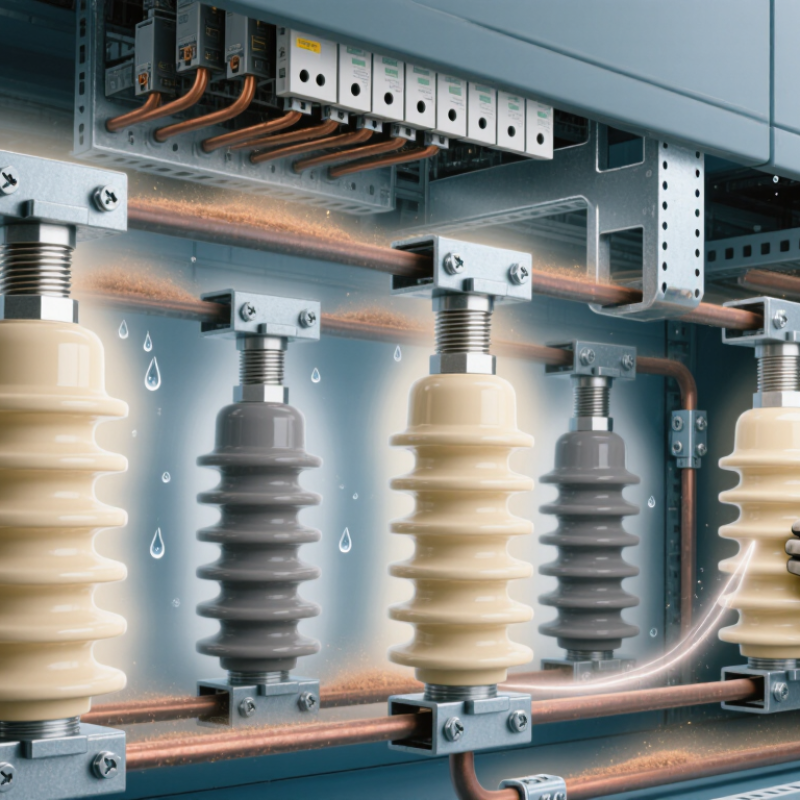
A Standoff Insualtor supports a conductor while keeping it physically separated from grounded metal or nearby components. That small distance can prevent arcing, tracking, and costly equipment damage. In a switchboard, the component may sit quietly beside a copper busbar. Yet heat, dust, vibration, and moisture constantly test its performance.

Dr. J. C. Fothergill, a recognized electrical-insulation researcher, observes, “Insulation is not merely a barrier; it is part of the electrical design.” This principle explains why engineers examine more than voltage ratings. They also consider creepage distance, clearance, material strength, thermal stability, and mounting torque. Ceramic standoff insulators often suit high-temperature environments. Polymer versions can reduce weight and simplify installation. The right choice depends on the complete operating condition.

A quality Standoff Insualtor also supports cleaner layouts. It can guide conductors through a compact enclosure without allowing unwanted contact. That matters in control panels, transformers, busbar assemblies, and printed circuit systems. Field experience shows that overlooked details cause many failures. A loose fastener, a cracked body, or surface contamination may remain invisible during normal operation.

No insulator solves every design problem. That is worth remembering. Engineers should verify spacing under real humidity, temperature, vibration, and fault conditions. Laboratory data may not perfectly represent a dusty factory floor. Careful selection, inspection, and scheduled maintenance make the component more dependable. In the end, choosing a Standoff Insualtor is not simply a purchasing decision. It is a decision about electrical separation, service life, and operational confidence.
Why Choose Standoff Insulators for Electrical Systems?

What Are Standoff Insulators and How Do They Work?

Standoff insulators are rigid supports that hold energized conductors away from panels, frames, and grounded metalwork. They create physical separation and provide electrical insulation at the same time. Common materials include porcelain, glass, and engineered polymers. Each insulator usually has a mounting hole and a shaped surface for securing a busbar or cable. When voltage is applied, the insulating body resists current flowing toward the mounting structure. Its shape also increases creepage distance along the surface. The principle sounds simple. The application is not.

In a real switchboard, a fastener carries mechanical stress while the insulator supports the conductor. Good selection considers system voltage, impulse withstand, creepage distance, temperature, contamination, and mechanical load. Current rating mainly belongs to the conductor, but nearby heat still affects the insulator.

Incorrect torque can crack ceramic parts or deform polymer materials. Dust and moisture may create tracking paths over time. A clean-looking support can still contain damage, so visual inspection alone is imperfect. Technicians should check for cracks, discoloration, looseness, and carbon marks before testing the system.

Tips: Match the insulator’s voltage and mechanical ratings with the design drawings. Keep required clearances around every energized part. Use calibrated tools when tightening hardware. De-energize and verify isolation before inspection. If conditions are dusty, wet, or chemically aggressive, review the creepage requirements again. Small installation details matter more than they first appear.

Key Materials and Design Features of Standoff Insulators

Why Choose Standoff Insulators for Electrical Systems?

Standoff insulators support energized conductors while maintaining a controlled distance from grounded panels. Their materials and geometry strongly influence safety, service life, and installation accuracy. Porcelain offers excellent dielectric strength and resists ultraviolet exposure, moisture, and heat. It is rigid, but sudden impact can cause cracking. Glass provides reliable insulation and visible fracture evidence, although it may be less forgiving during handling.

Epoxy and thermoset polyester are common choices for compact, lightweight assemblies. These polymers allow precise shapes, threaded inserts, and integrated mounting features. Good formulations resist tracking, flame, and thermal cycling. However, resin performance depends on cleanliness, curing quality, and the surrounding temperature. No material is perfect. Field inspections often reveal contamination around mounting points, where dust and moisture reduce surface insulation.

Design details matter as much as material selection. Deep ribs increase creepage distance and help interrupt surface leakage paths. Smooth edges reduce local electric-field concentration. Reinforced holes prevent stress around bolts, while accurate tolerances keep conductors aligned under vibration. Clearance must account for voltage, altitude, pollution, and expected movement. A small washer may change the effective spacing. Engineers should verify both dry and humid conditions, rather than trusting a drawing alone. One overlooked issue is tightening force; excessive torque can damage polymer bodies without visible marks. Practical testing, documented material data, and careful inspection provide stronger reliability than appearance alone.

Why Choose Standoff Insulators for Electrical Systems? - Key Materials and Design Features of Standoff Insulators
Material or Design Feature Typical Electrical Performance Temperature Capability Key Advantages Primary Limitations Common Applications
Alumina or Steatite Ceramic High dielectric strength and stable insulation resistance; performance is generally maintained over a wide frequency and temperature range. Often suitable for continuous service above 200°C, depending on grade, geometry, glaze, and mounting hardware. Excellent dimensional stability, high compressive strength, strong resistance to arcing, chemicals, and ultraviolet exposure. Brittle; vulnerable to impact and tensile stress. Machining and complex shapes can increase cost. Switchgear, busbar supports, high-voltage assemblies, furnaces, test equipment, and outdoor electrical hardware.
Glass-Filled Epoxy High insulation resistance and good dielectric strength; suitable for low- and medium-voltage support components when properly designed. Common continuous-use ranges are approximately 100–155°C, depending on resin system and certification. Good mechanical strength, low moisture absorption, accurate molding, and convenient threaded or molded mounting features. Can be affected by prolonged ultraviolet exposure, high humidity, thermal cycling, or surface tracking if contamination is present. Indoor switchboards, busbar supports, control cabinets, transformers, and power distribution equipment.
Polyester-Based Thermoset Provides reliable insulation for many low- and medium-voltage applications; electrical properties depend strongly on filler content and formulation. Typically used in moderate-temperature environments, commonly around 80–130°C continuous service. Cost-effective, lightweight, corrosion-resistant, and suitable for compression molding with integrated mounting features. Lower long-term heat, impact, and tracking resistance than many ceramic or high-performance epoxy materials. Panelboards, terminal supports, control equipment, motor assemblies, and indoor distribution systems.
High-Temperature Thermoplastic Good insulation resistance with consistent molded dimensions; electrical performance varies by polymer type, reinforcement, and operating environment. Specialized grades can support continuous operation around 120–180°C; standard grades may be lower. Lightweight, impact-resistant, fast to manufacture, and well suited to complex shapes and snap-fit or threaded designs. May creep under sustained mechanical load and can be sensitive to chemicals, heat, or ultraviolet exposure depending on polymer grade. Compact control devices, electronic power assemblies, relay systems, and indoor equipment with moderate mechanical loads.
Silicone Rubber Housing or Coating Provides good surface insulation and hydrophobic behavior; commonly used as an exterior covering rather than the sole structural material. Many electrical-grade silicone systems support approximately −50°C to 180°C, subject to formulation and aging conditions. Excellent weatherability, flexibility, resistance to ultraviolet radiation, and strong performance in contaminated outdoor environments. Lower structural stiffness than ceramic or rigid thermosets; may require a rigid core and careful control of mechanical loading. Outdoor insulation, compact medium-voltage equipment, pollution-resistant assemblies, and areas with condensation or salt exposure.
Cylindrical or Ribbed Profile Increases creepage distance and helps control surface leakage current under wet or contaminated conditions. Temperature capability is determined mainly by the selected insulating material and mounting hardware. Improves pollution performance without requiring a proportional increase in overall height. Ribs can collect dust or ice if the profile is poorly selected for the environment; cleaning access may be necessary. Outdoor switchgear, busbar systems, distribution equipment, and installations exposed to moisture or industrial pollution.
Solid One-Piece Body Reduces internal interfaces and potential moisture paths, supporting consistent dielectric performance. Limited by the thermal rating of the body material, inserts, fasteners, and connected conductors. Simple construction, high reliability, reduced assembly count, and easier inspection. May provide less flexibility for thermal expansion or complex routing than multi-part designs. Busbar supports, terminal blocks, compact switchgear, and general electrical mounting assemblies.
Metal Threaded Inserts Maintain mechanical attachment while the insulating body provides electrical separation from the mounting surface. Insert material and installation torque must be compatible with the insulator’s thermal rating. Secure fastening, repeatable installation, improved load transfer, and easier replacement. Improper torque, sharp edges, or insufficient creepage around the insert can create mechanical or electrical failure points. Busbar supports, panel assemblies, transformer components, and equipment requiring bolted connections.
Designed Creepage and Clearance Clearance limits breakdown through air; creepage controls leakage and tracking along the insulating surface. Required distances may need adjustment for altitude, humidity, pollution level, and operating voltage. Supports dependable voltage isolation and helps meet electrical safety and coordination requirements. Insufficient spacing, contamination, condensation, or incorrect installation can reduce insulation performance. All standoff insulator installations, especially switchgear, power supplies, busbars, and outdoor systems.
Typical performance depends on material grade, dimensions, voltage, frequency, altitude, humidity, pollution, mounting torque, and applicable testing standards. Final selection should be verified against the equipment design and the relevant electrical safety requirements.

Electrical and Mechanical Benefits in System Applications

Why Choose Standoff Insulators for Electrical Systems?

Standoff insulators create a firm gap between energized conductors and grounded structures. This separation supports safer electrical layouts and cleaner panel construction. In practical panel work, the right spacing reduces accidental contact risks and helps control surface leakage. Their insulating body also resists current flow through mounting points. That matters in compact switchboards, busbar supports, and equipment cabinets.

The mechanical benefits are equally important. A well-selected standoff insulator supports conductors against vibration, shock, and moderate thermal movement. It also helps maintain alignment when cables or busbars experience pulling forces. Materials should be chosen for voltage, temperature, moisture, contamination, and expected mechanical load. Surface distance deserves careful attention too. Longer creepage paths can improve performance in dusty or humid environments. Small details matter.

Installation quality can weaken good design. Excessive tightening may crack the insulator or distort its mounting point. Loose hardware can allow movement, noise, and gradual wear. No component is perfect. Engineers should verify clearances, torque values, and temperature limits against applicable standards. A field inspection may reveal problems that drawings miss. I have found that simple checks, such as looking for stress marks or uneven spacing, often prevent larger failures. This step is easy to neglect. That deserves reflection.

Why Choose Standoff Insulators for Electrical Systems?

Standoff insulators provide electrical isolation while mechanically supporting conductors and busbars. The representative ranges below show common material-property values used when evaluating electrical and mechanical performance in system applications.

Values are representative engineering ranges for commonly used insulating materials; actual performance depends on design, standards, temperature, contamination, mounting method, and manufacturer specifications.

How to Select the Right Standoff Insulator

Selecting the right standoff insulator begins with the electrical system, not the catalog shelf. Define the working voltage, peak voltage, and required insulation level. Then check creepage and clearance distances. Humid or dusty locations need more surface distance. Small gaps can become serious weaknesses.

Material choice matters just as much. Porcelain handles heat well, while engineering polymers can reduce weight and simplify installation. Check temperature limits, flame behavior, moisture absorption, and resistance to tracking. The insulator must also support the conductor’s weight and fault forces. Measure mounting holes carefully. A perfect electrical rating cannot repair poor alignment.

During panel inspections, I look for cracks, loose hardware, sharp edges, and compressed mounting surfaces. These details are easy to miss. Thread strength and torque recommendations deserve equal attention. For outdoor equipment, review ultraviolet exposure, rain, pollution, and freeze-thaw conditions. For indoor systems, chemical vapors may matter more than weather. Select products tested against recognized electrical and mechanical requirements, then verify their certificates and test conditions. A laboratory result may not match your installation exactly. Field checks still matter. Sometimes a slightly larger insulator provides better clearance and easier maintenance, but it may create space problems. Record the final dimensions, materials, ratings, and installation torque before approval.

Installation, Maintenance, and Safety Considerations

Standoff insulators keep energized conductors separated from panels, frames, and grounded surfaces. During installation, select the correct voltage rating, creepage distance, and mechanical strength. Measure the mounting position before drilling. Small alignment errors can stress the insulator.

Use compatible bolts, washers, and conductor supports. Tighten fasteners to the specified torque, not simply until they feel tight. Over-tightening may cause hidden cracks. Keep sharp edges away from the insulating body. Leave enough clearance for tools, heat, and conductor movement. A rushed installation can look acceptable.

Maintenance should follow a written inspection schedule. Look for cracks, tracking marks, discoloration, loose hardware, dust, and moisture. Clean surfaces with approved methods after isolating the circuit. Avoid abrasive materials that create scratches. Check cable weight and vibration after installation. These details are easy to overlook.

Safety comes first. De-energize, lock out, and verify the absence of voltage with a properly rated tester. Wear task-appropriate protective equipment. Never rely on an insulator as proof that a circuit is safe. A visual check alone can miss internal damage. Thermal scanning may reveal abnormal heating near connections, but it does not replace electrical testing. Records should include inspection dates, findings, torque checks, and corrective actions. Review them carefully. Human error remains possible.

FAQS

What is a standoff insulator?

It is a rigid support for energized conductors. It keeps them away from grounded panels and metal frames. It provides spacing and electrical insulation. Its shaped surface holds a busbar or cable.

How does a standoff insulator prevent unwanted current flow?

The insulating body resists current moving toward the mounting structure. Its shape also increases the surface creepage distance. Longer paths can reduce leakage across dusty or damp surfaces. The principle is simple. The application is not.

Which materials are commonly used?

Common materials include porcelain, glass, epoxy, and thermoset polyester. Porcelain handles heat, moisture, and ultraviolet exposure well. Glass can show visible fracture damage. Polymer materials are lightweight and support precise shapes. No material is perfect.

What should engineers consider during selection?

Check voltage, impulse withstand, creepage distance, temperature, contamination, and mechanical load. Consider altitude and expected movement too. Match these values with the design drawings. A small washer can change the actual spacing.

Does the insulator carry the conductor’s current rating?

The conductor mainly determines current rating. However, nearby heat still affects the insulator. Temperature limits must match the application. A support may look suitable but still overheat in a compact cabinet.

What mechanical problems can occur?

Loose hardware can cause movement, noise, and gradual wear. Excessive torque can crack ceramic parts or deform polymer bodies. Vibration may worsen small mounting defects. Use calibrated tools. Tightening is easy to underestimate.

How should a standoff insulator be inspected?

De-energize the system and verify isolation before inspection. Look for cracks, discoloration, looseness, stress marks, and carbon traces. Check for uneven spacing around energized parts. Visual inspection alone is imperfect. Hidden damage may remain.

How do dust and moisture affect performance?

Dust and moisture can create surface tracking paths. Contamination reduces effective insulation along the creepage route. Review creepage requirements in wet, dusty, or chemically aggressive areas. Clean conditions can change over time. Plan for reality, not appearance.

Why are clearances and creepage distances both important?

Clearance is the direct air gap between conductive parts. Creepage is the distance along the insulating surface. Both must suit voltage and environmental conditions. Deep ribs can lengthen the surface path. Drawings may not show every field problem.

Conclusion

Standoff insulators are essential components in electrical systems, designed to support and separate energized conductors from mounting surfaces while maintaining a reliable insulation barrier. A Standoff Insualtor typically uses materials such as porcelain, glass, or engineered polymers, selected for their dielectric strength, durability, resistance to heat, moisture, chemicals, and environmental aging. Its shape, creepage distance, mounting structure, and connection points are carefully designed to meet specific voltage and mechanical requirements.

By preventing unwanted current flow and maintaining conductor spacing, standoff insulators improve electrical safety, system stability, and equipment service life. They can also withstand vibration, tension, compression, and other mechanical stresses in indoor or outdoor applications. Choosing the right type requires evaluating operating voltage, load requirements, environmental conditions, dimensions, and installation standards. Proper installation should include secure fastening, correct alignment, adequate clearance, and inspection for cracks, contamination, or damage. Routine maintenance and safe handling help preserve insulation performance and reduce the risk of electrical faults.

Ethan

Ethan

Ethan is a seasoned marketing professional with a deep expertise in our company's innovative product line. With a passion for sharing knowledge and insights, he takes the lead in regularly updating our corporate blog, where he explores industry trends, product features, and effective marketing......